Product Categories


Fortron/Source is a multinational corporation with offices, R&D centers and manufacturing locations in the USA and China. We provide ODM and OEM services for customers all around the world. Our China facilities focus on power supply manufacturing services and our USA facility provides PCBA and system assembly services for our customers.
Advantages

Established Brand

Reliable Service

Experienced Management

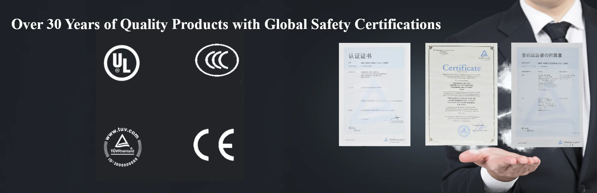
Quality Product

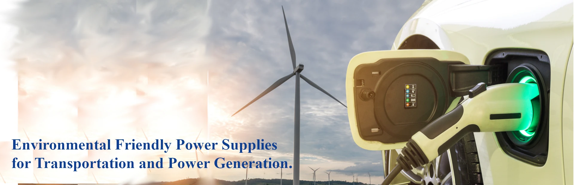
EV Charger
Max. 32Amp
SAE J1772 Connectors

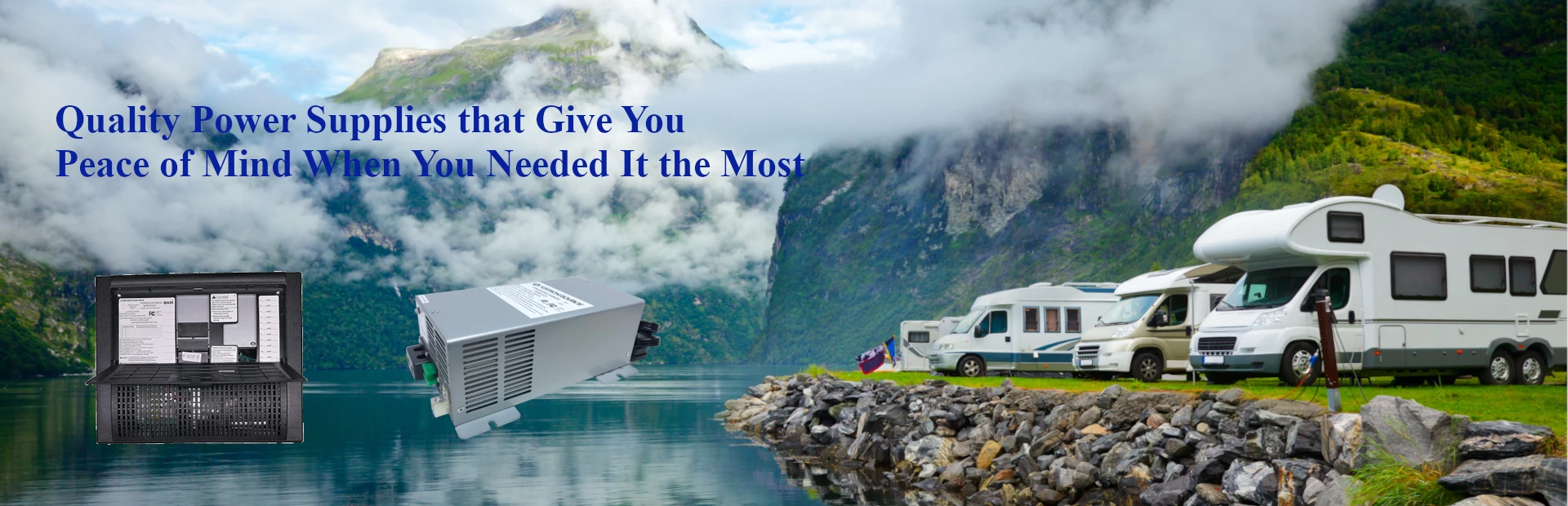
RV Charger
220W~1400W UL458 certification
Output voltage
13.6 VDC
MTBF Life> 1 Million Hours


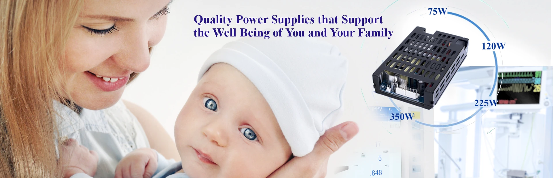
EN60601-1 Power Supply
Power: 75W~350W
Medical (BF) Safety Certification

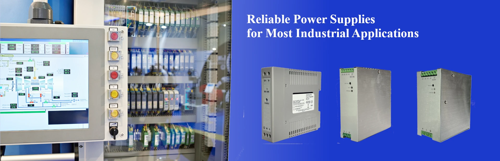
Industrial Power Supply
75W~350W UL60950 certification
MTBF Life> 1 Million Hours

ODM POWER SERVICES
Fortron/Source has been manufacturing power supplies for our customers during the past 30 years. We can manufacture in China or USA, depending on our customers’ requirements. Also we have R&D facilities in China and USA, so we can rapidly design power supplies to meet the needs of our customers around the globe.